Relief duty & set pressure
State the required set pressure, relieving conditions and capacity. Include inlet and outlet connections, backpressure and the medium for sizing.
Your products and information will be ready in a moment.
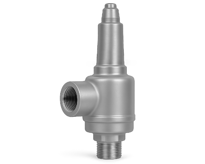
| Available Sizes | DN15-DN25 |
|---|---|
| Connection Type | BSP · NPT |
| Size | DN15 · DN20 · DN25 |
| Body Material | CF8 |
| Seat Material | HPb59-1 |
| Disc Material | HPb59-1 |
| Media | LNG. LO2. LN2. LAr, CO2 |
| Thread Type | Female |
Catalogue options. Operating limits depend on the selected size, materials and configuration.
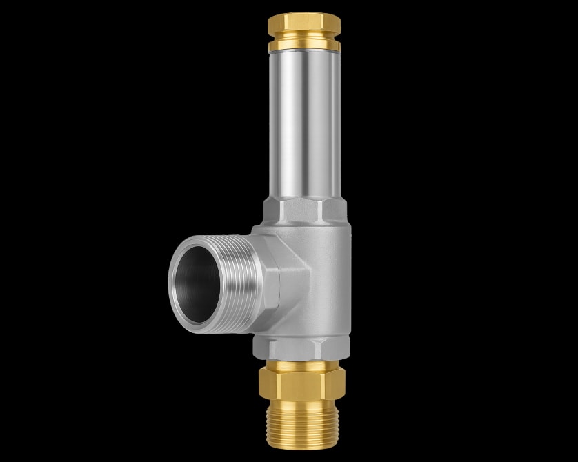
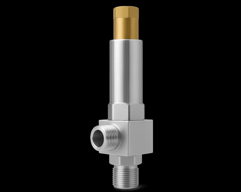
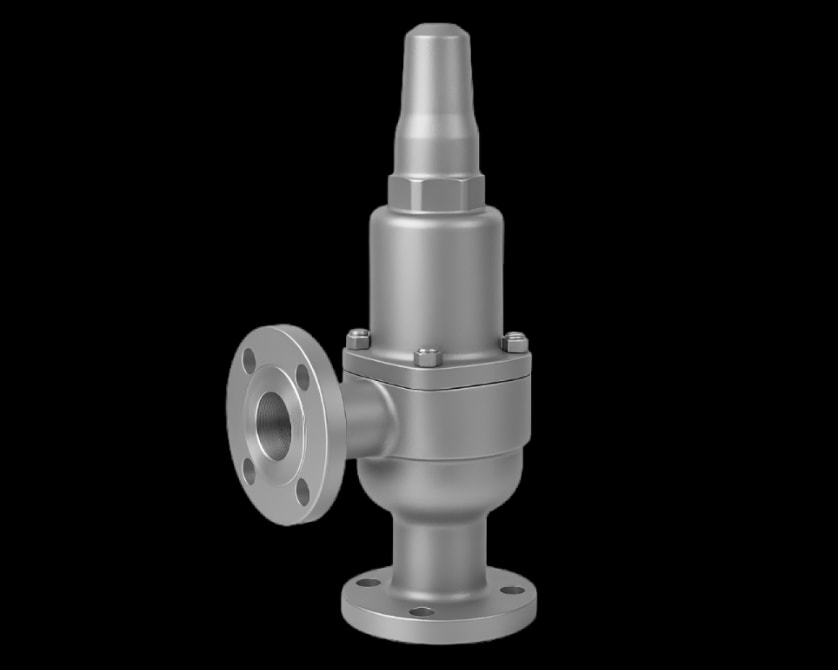
Cryogenic safety valve with a CF8 body and female BSP or NPT connections for pressure-relief duties. Provide the set pressure, relieving capacity, medium, temperature and outlet backpressure for sizing.
Applications: Cryogenic applications
For technical documentation or assistance with your selection, contact Nordic Valves.
Cryogenic safety valve with a CF8 body and female BSP or NPT connections for pressure-relief duties. Provide the set pressure, relieving capacity, medium, temperature and outlet backpressure for sizing.
| Specification | Catalogue data |
|---|---|
| Size range | DN15-DN25 |
| Connection | Female threaded, BSP / NPT |
| Pressure / setting | Specify rating and required set pressure |
| Operation | Spring-loaded pressure relief |
| Source temperature* | -196°C to +80°C |
| Catalogue media | LNG, LOX, LN2, LAr, CO2 |
Catalogue options. Nominal ratings are not the allowable pressure at every temperature; confirm the selected configuration. *Documented family temperature range; confirm pressure-temperature limits and the selected trim.
| Component | Catalogue material |
|---|---|
| Body | CF8 |
| Seat | HPb59-1 |
| Disc | HPb59-1 |
Materials shown are the published catalogue construction. Confirm seat, seals and any service-specific trim with the quotation.
| DN | H | H1 | M1 | M2 | L | Operating pressure (MPa) | Set pressure (MPa) |
|---|---|---|---|---|---|---|---|
| 15 | 150 | 56 | G3/4 | M30x1.5 | 35 | 4.0 | 0.4 - 1.0 |
| 15 | 150 | 56 | G3/4 | M30x1.5 | 35 | 4.0 | 1.0 - 2.0 |
| 15 | 150 | 56 | G3/4 | M30x1.5 | 35 | 4.0 | 2.0 - 3.0 |
| 25 | 197 | 69 | G1 1/4 | M36x2 | 47 | 4.0 | 0.4 - 1.0 |
| 25 | 197 | 69 | G1 1/4 | M36x2 | 47 | 4.0 | 1.0 - 2.0 |
| 25 | 197 | 69 | G1 1/4 | M36x2 | 47 | 4.0 | 2.0 - 3.0 |
Linear and diameter dimensions are in mm; weights are in kg. Pressure bands are in MPa (1 MPa = 10 bar). Height and length datums follow the drawing. Thread designations and ISO mounting codes are not linear dimensions. Supplied female-threaded relief arrangement, DN15 and DN25. M1/M2 are the exact source connection designations, including metric threads; do not substitute BSP/NPT. DN20 is not tabulated. Set-pressure bands do not establish relief capacity. Use the approved order drawing for installation and fabrication.
| Component | Source arrangement material |
|---|---|
| Cover | HPb59-1 |
| Spring Seat | S30408 |
| Adjusting Ring | HPb59-1 |
| Adjusting Screw | HPb59-1 |
| Ejector Bar | 20Cr13 |
| Body | S30408 |
| Lock Nut | S30408 |
| Spring | S30210 |
| Sealing | T2 |
| Sealing | PTFE |
| Disc | S32168 |
| Valve Seat | S32168 |
| Bonnet | S30408 |
Materials apply to the supplied reference arrangement. Supplied female-threaded relief arrangement, DN15 and DN25. M1/M2 are the exact source connection designations, including metric threads; do not substitute BSP/NPT. DN20 is not tabulated. Set-pressure bands do not establish relief capacity.
| Engineering data | Configuration requirements |
|---|---|
| Dimension data | Reference table and drawing: DN15, DN25. Dimensions and connection reference. |
| Installation drawing | Confirm BSP or NPT, male/female ends, thread sizes, engagement, end-to-end length and installation clearance. |
| Pressure-temperature rating | Confirm allowable inlet pressure at the relieving temperature for the selected body, trim and seals. Specify set pressure, back pressure and certified relief capacity separately. |
Nominal pressure class, temperature range and relief set pressure are separate specifications. Confirm the allowable pressure at the design temperature for the selected construction.
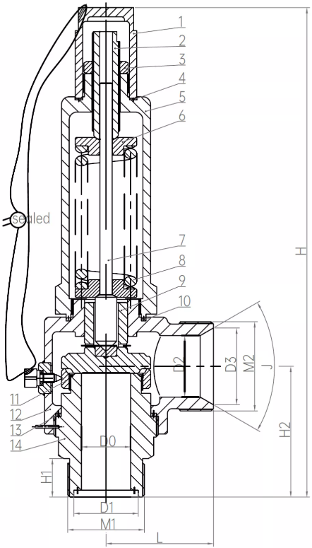
Supplied female-threaded relief arrangement, DN15 and DN25. M1/M2 are the exact source connection designations, including metric threads; do not substitute BSP/NPT. DN20 is not tabulated. Set-pressure bands do not establish relief capacity.
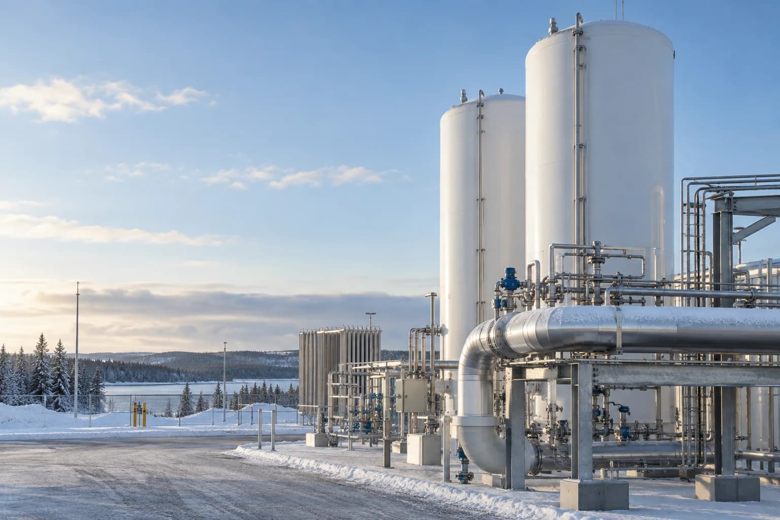
Valves for liquefied-gas transfer and storage, with options for stem extensions, end connections and pressure relief.
Explore application guidanceState the required set pressure, relieving conditions and capacity. Include inlet and outlet connections, backpressure and the medium for sizing.
Specify the medium, minimum temperature and operating pressure. Include stem-extension needs, insulation clearance and any oxygen-cleaning requirements in your enquiry.
Listed body options: CF8. seat or seal options: HPb59-1. Match the selected combination to the medium and operating temperature.
Include the operating conditions in your enquiry. Add your medium, pressure, temperature and documentation requirements alongside the selected options.
Review quotation basket