Flow & differential pressure
Provide design flow, available differential pressure and the required balancing or control function. For electric control, include voltage, signal, fail position and feedback requirements.
Your products and information will be ready in a moment.
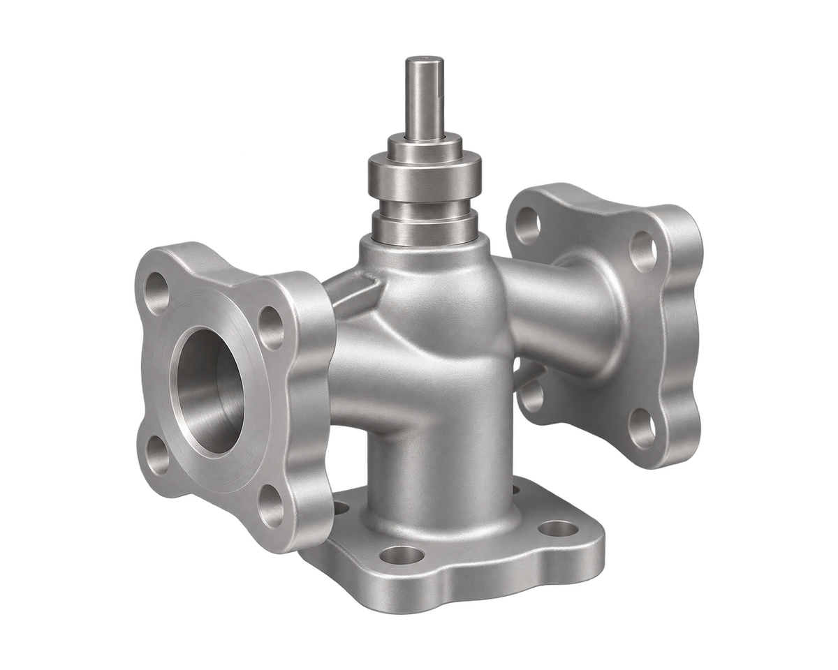
| Model Reference | 6171K |
|---|---|
| Available Sizes | DN15-200 |
| Requested Size | DN15 · DN20 · DN25 · DN32 · DN40 · DN50 · DN65 · DN80 · DN100 · DN125 · DN150 · DN200 |
| Pressure Rating | PN16 · PN25 |
| Body Material | Stainless Steel SS304 |
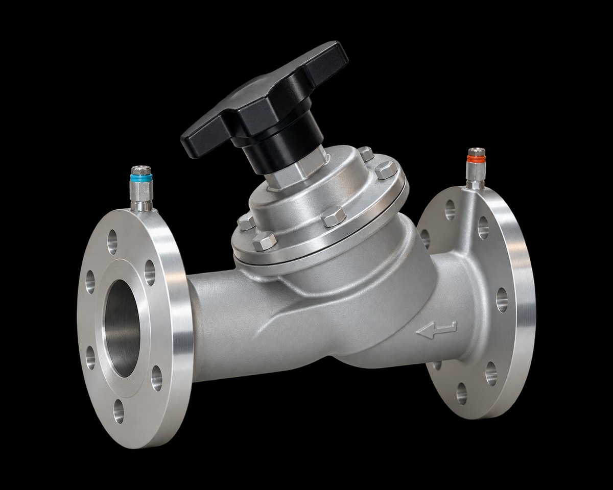
| Connection Type | Flanged |
| Working Temperature | -10°C to 150°C |
| Suitable Medium | Water; ethylene glycol solution up to 50% concentration |
| Selection Basis | Catalogue range; exact size, pressure, materials and coolant compatibility confirmed for the project |
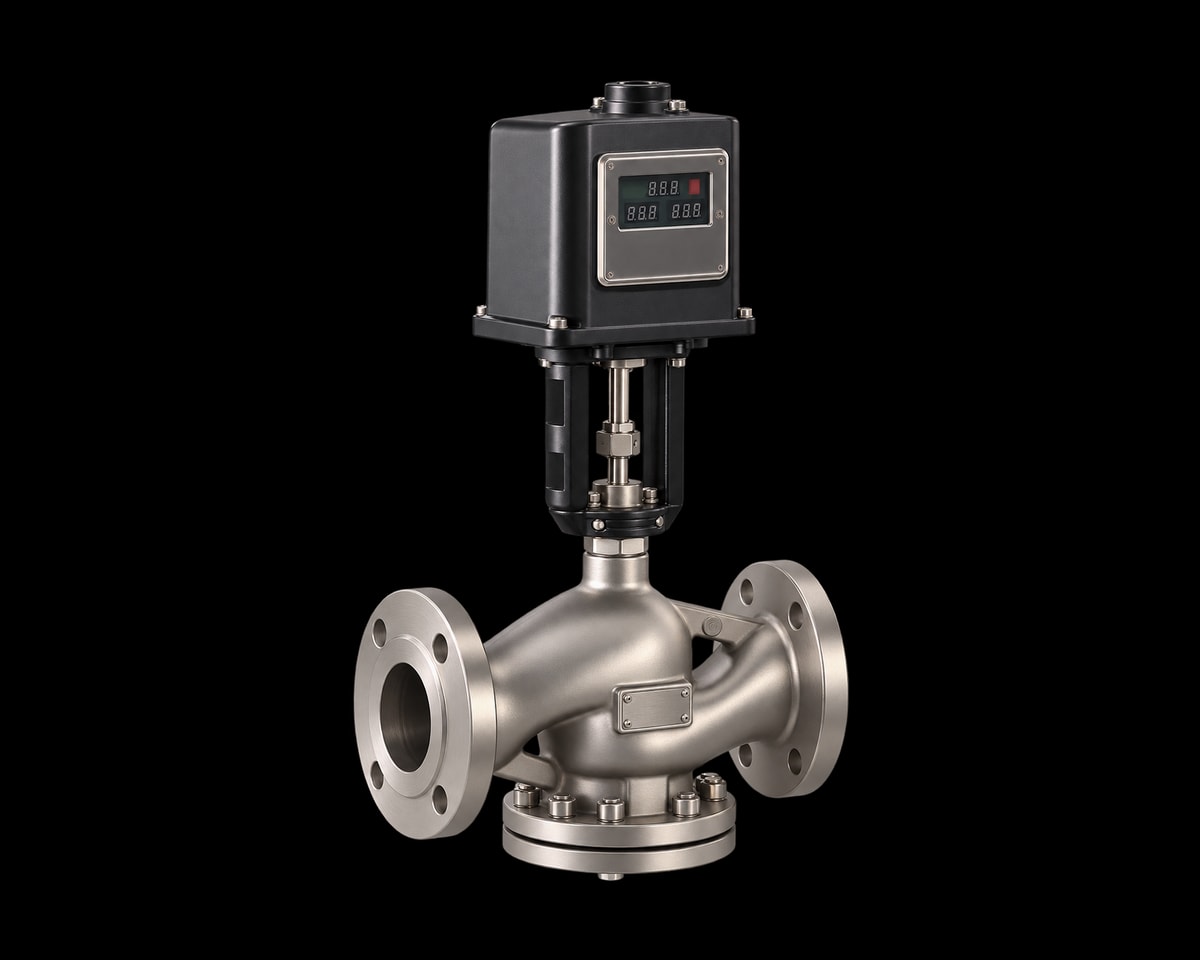
| Control Function | Three-way electric control |
| Actuator Selection | GSX / GSV; voltage and signal depend on actuator model |
| Actuator Model | GSX11 · GSX16 · GSX31 · GSV11 · GSV16 · GSV31 |
| Control Signal Range | 0–10 V · 2–10 V · 4–20 mA · 0–20 mA · Incremental signal |
| Feedback Signal Range | 0–10 V · 2–10 V · 4–20 mA · 0–20 mA · No feedback |
Catalogue options. Operating limits depend on the selected size, materials and configuration.
Three-way control for mixing or diverting duties as defined by the selected flow arrangement. Confirm port layout, Kvs and actuator selection.
Applications: Data Centers & AI Cooling
For technical documentation or assistance with your selection, contact Nordic Valves.
Three-way control for mixing or diverting duties as defined by the selected flow arrangement. Confirm port layout, Kvs and actuator selection.
| DN | INCH | C / mm | L / mm | D, mm / PN16 | D, mm / PN25 | D1, mm / PN16 | D1, mm / PN25 | n*φd / PN16 | n*φd / PN25 | f / mm | H / mm | H2 / mm |
|---|---|---|---|---|---|---|---|---|---|---|---|---|
| 15 | ½" | 13 | 122 | 95 | 95 | 65 | 65 | 4*φ14 | 4*φ14 | 2 | 136 | 66 |
| 20 | ¾" | 14 | 130 | 105 | 105 | 75 | 75 | 4*φ14 | 4*φ14 | 2 | 136 | 70 |
| 25 | 1" | 15 | 140 | 115 | 115 | 85 | 85 | 4*φ14 | 4*φ14 | 2 | 137 | 80 |
| 32 | 1¼" | 17 | 180 | 140 | 140 | 100 | 100 | 4*φ18 | 4*φ18 | 2 | 138 | 92 |
| 40 | 1½" | 17 | 200 | 150 | 150 | 110 | 110 | 4*φ18 | 4*φ18 | 2 | 150 | 101 |
| 50 | 2" | 18 | 230 | 165 | 165 | 125 | 125 | 4*φ18 | 4*φ18 | 2 | 154 | 116 |
| 65 | 2½" | 18 | 290 | 185 | 185 | 145 | 145 | 4*φ18 | 8*φ18 | 2 | 205 | - |
| 80 | 3" | 18 | 310 | 200 | 200 | 160 | 160 | 8*φ18 | 8*φ18 | 2 | 214 | - |
| 100 | 4" | 20 | 350 | 220 | 235 | 180 | 190 | 8*φ18 | 8*φ22 | 2 | 241 | - |
| 125 | 5" | 20 | 400 | 250 | 270 | 210 | 220 | 8*φ18 | 8*φ26 | 2 | 270 | - |
| 150 | 6" | 22 | 480 | 285 | 300 | 240 | 250 | 8*φ22 | 8*φ26 | 2 | 292 | - |
| 200 | 8" | 22 | 495 | 340 | 360 | 295 | 310 | 12*φ22 | 12*φ26 | 2 | 333 | - |
Dimensions use the letter references in the datasheet drawing. Pressure-class columns refer to the specified flange drilling.
| Drawing no. | Part | Material | Specification |
|---|---|---|---|
| 1 | Body | Stainless Steel | SS304 |
| 2 | Core | Stainless Steel | -- |
| 3 | Stem | Stainless Steel | -- |
| 4 | Sealing | Special sealing combination (confirm specification) | -- |
Material options are shown where listed. Confirm the complete wetted construction for the selected coolant and configuration.
| DN | INCH | Kvs | Stroke / mm | Standard Driver Model | Maximum Closing Pressure Difference Ps, Mpa △ |
|---|---|---|---|---|---|
| 15 | ½" | 4 | 20 | GSX Series | ≤0.80 |
| 20 | ¾" | 5 | 20 | GSX Series | ≤0.80 |
| 25 | 1" | 7.5 | 20 | GSX Series | ≤0.80 |
| 32 | 1¼" | 10 | 20 | GSX Series | ≤0.80 |
| 40 | 1½" | 12 | 20 | GSX Series | ≤1.60 |
| 50 | 2" | 31 | 20 | GSX Series | ≤0.60 |
| 65 | 2½" | 49 | 20 | GSX Series | ≤0.45 |
| 80 | 3" | 78 | 20 | GSX Series | ≤0.45 |
| 100 | 4" | 124 | 20 | GSX Series | ≤0.20 |
| 125 | 5" | 200 | 40 | GSV Series | ≤0.15 |
| 150 | 6" | 300 | 40 | GSV Series | ≤0.10 |
| 200 | 8" | 450 | 40 | GSV Series | ≤0.13 |
Use Kvs and the maximum closing differential pressure to select the valve and actuator together. Characteristic curves, wiring and calibration instructions are in the datasheet.
| Actuator | Valve size | Supply / AC | Control signal | Feedback signal | Force / N |
|---|---|---|---|---|---|
| GSX11 | DN15–100 | 24 V, 50/60 Hz | Incremental | — | 1500 |
| GSX16 | DN15–100 | 24 V, 50/60 Hz | 0–10 V or 4–20 mA | 0–10 V or 4–20 mA | 1500 |
| GSX31 | DN15–100 | 220 V, 50/60 Hz | Incremental | — | 1500 |
| GSV11 | DN125–200 | 24 V, 50/60 Hz | Incremental | — | 2800 |
| GSV16 | DN125–200 | 24 V, 50/60 Hz | 0–10 V or 4–20 mA | 0–10 V or 4–20 mA | 2800 |
| GSV31 | DN125–200 | 220 V, 50/60 Hz | Incremental | — | 2800 |
Select the valve Kvs, maximum closing differential pressure and actuator together. Wiring and calibration instructions are in the datasheet. Confirm any required fail position for the project.
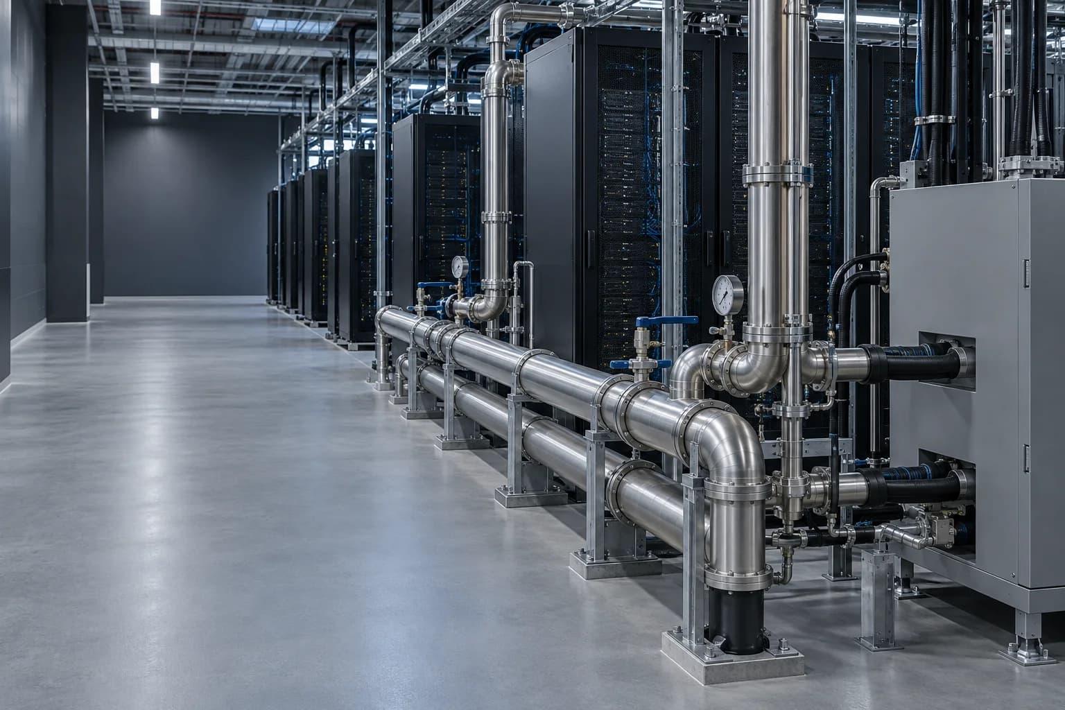
Isolation, balancing, control valves, strainers and flexible connections for facility-water and CDU cooling circuits.
Explore application guidanceProvide design flow, available differential pressure and the required balancing or control function. For electric control, include voltage, signal, fail position and feedback requirements.
State facility-water or CDU / technology-cooling duty, coolant formulation, flow, temperature and pressure. Confirm wetted materials and the exact valve configuration for the project.
Include the required installation drawing, material documentation and testing requirements. Confirm the final configuration and its operating limits with your enquiry.
Include the operating conditions in your enquiry. Add your medium, pressure, temperature and documentation requirements alongside the selected options.
Review quotation basket